


How to Optimize EMI Test by TEM cell
Click Here to Download the PDF version
Abstract
Generally speaking, traditional EMI radiation emission tests are usually conducted in large shielding rooms, using diversified antennas to obtain radiated signals. Due to bandwidth limitations, multiple antennas are required to cover the entire frequency range. In addition, it requires a lot of space, and the equipment cost for standard consistency settings is higher than as usual.
Engineers in small and medium-sized enterprises usually have to rely on his experience and best practices to design EMC-compliant products. However, it is estimated that more than 50% of products fail the test in the first test. Whenever an engineer sends a new product to a compliance testing laboratory. The cost of failure rate is very expensive. Not only is the cost of retesting high, but the cost of adjustments in certified laboratories is also very expensive, usually charging up to US $ 150 per hour, and the project schedule and marketing are delayed. It causes the new product can not be announced smoothly in a timely manner.
TEM Cell Introduction
In fact, what engineers need is a reasonably priced laboratory that can measure the radiation emissions in their own laboratory before compliance testing. The TEM cell is the correct device for desktop testing of radiated emissions. The R & D team on the market recently developed an open TEM cell to cover the entire frequency range up to 2GHz, and it is available even at higher frequencies.

** The Radiation Test structure by TEM Cell **
This TEM cell can be used in conjunction with a spectrum analyzer to test products before and after EMC-related design modifications. Devices with TEM batteries cannot provide exactly the same quantitative results as measurements made in a certified test room, but it will be a good indication of whether the design has suffered too much radiated noise. The engineer will clearly see whether his changes improve or degrade EMC performance, or whether it remains the same. Using the TEM cell eliminates most of the unnecessary background interference.
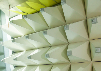
The TEM cell is a strip-line device used for radiated emission and immunity tests of electronic devices. It is not a substitution, but because of its size and cost, it is a convenient alternative to measurements in a shielding room. The TEM cell consists of a diaphragm, a conductive strip in the central part and a grounded wall. The geometry is designed to present a 50Ω strip-line. The device under test (DUT) is placed between the bottom wall and the septum. It has no side walls to facilitate the placement of DUT. It may pick up RF background noise, but it can be taken into account by measuring the output signal of the unit before powering up the DUT. Compared with standard TEM cells of similar size, general open TEM cells have better frequency response. TEM cells suffer from the limitation of higher-order wave modes, which limit the available bandwidth. The unique design function of the specially made TEM unit realizes the resistance perpendicular to the desired wave propagation direction. Therefore, higher-order mode and resonance are suppressed. All TEM cells are supplied with 50Ω / 25W RF terminations to protect the DC module of the spectrum analyzer or RF receiver input and N-Male to N-Male coaxial cable.

** Simulated Diagram of TEM Cell Device **
RIGOL EMI Test Solution with TEM Cell Device
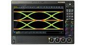
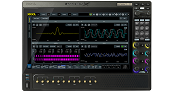
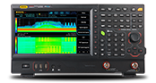
Today we take a medical heartbeat pacemaker as an example. Because it is a medical level product, the requirements for EMI test certification are particularly strict. The working frequency of most medical-grade electronic instruments and equipment is very low, so it is necessary to strictly filter out the background noise to observe the true EMI characteristics and performance, so TEM Cell is a good auxiliary tool. We placed the motherboard of the heartbeat pacemaker in the TEM Cell, and connected one end of the TEM Cell to the SMA receiving terminal of the RIGOL RSA5065 real-time spectrum analyzer, and the other end was connected to a 50 Ohm terminator, so that it would not happen The reflected noise in turn affects EMI testing. Next, set the RSA5065 spectrum analyzer in the EMI option operation mode to start measurement. We first scan the EMI traces without placing the TEM Cell. The yellow Trace 1 result can be obtained. And set the detector mode of Peak detection, Quasi-Peak detection and Average detection respectively, turn on the Meter function, and then set the limit value of the Limit Line standard. After completing the first stage of scanning, place the motherboard in the TEM Cell, then open the Trace 2, and rescan again to get the green Trace 2. According to the scanning solution results, it can be found that after adding the TEM Cell, the noise floor part is obviously reduced a lot, which is the only contribution of the TEM Cell.

**RSA5065 Spectrum Analyzer with TEM Cell for Pacemaker EMI Test**

*** EMI test result without TEM Cell ***

*** EMI Test result comparison between with and without TEM Cell ***